

Homemade Drawing/Engraving Machine
CAM project (computer-aided manufacturing)
This article describes, step by step, how to build a drawing machine in Solidworks. It also shows how to use stepper motors and microcontrollers to control a pen capable of drawing any image. Two versions were created, one using profiles, the other being fully 3D printable. This machine will be transformed into an engraving machine in the future.
GitHub link: https://github.com/Apiquet/drawing_machine
First, I will show what I have achieved in this project. Then I will explain how to use SolidWorks to create a part and an assembly that combines several parts. I will also go a bit further by explaining some useful features: making mirrors for symmetrical parts, a thread, a net, how to convert an image into a model, etc. Finally, I will post the complete video of the implementation of the V2 module, which was the most complete task done.
Table of contents
- Two versions built
- V1 with profile
- V2 without profile
- Solidworks
- The basics
- Some usefull features
- Convert a part for our 3D printer
- Some parts creation in V1 machine
- Parts creation in V2 machine
- Printing
- Assembly
- Module assembly
- Y-axis assembly
- X-axis assembly
- Addition of the belts
- Motors and servo control
- Result
- Upgrade to engraving machine
1) Two versions built
1-a) V1 with profile
This first version I have made use profiles. It brings rigidity and makes it possible to have a machine with a larger wingspan. Here is an animation of the version, all parts are available on my github:
1-b) V2 without profile
Then, I decided to create another version which does not need profiles. This is a smaller version more portable and completely printable in 3D. This version fit more my usecase of having a machine I can assemble in a few minutes. The following animation shows how light the machine is:
2) Solidworks
2-a) The basics
In Solidworks, to start a piece, we must select a plan, create a sketch (the piece in 2D) then define the dimension of each segments with the Smart Dimension option. Finally, we need to extrude it to get our piece in 3D. For instance, these steps are done as follow to create a simple rail:
We can then update this document in two ways: by adding or deleting material. The principle is the same, we must first define the 2D sketch plan, then its drawing, and finally choose to extrude or cut. To keep the same example, we might want to add a wall and a hole in it to fix the rail against something:
The last thing you need to know is how to create the assembly and the mates. This is important because it allows you to take several parts and assemble them to create a machine. Thanks to this, we can check if the dimensions of each part are correct and if the whole machine is viable. First, we need to start from a piece and select “Make assembly from part”. Then, you can insert as many pieces as you want. To make them work together, we have to create Mates, these are constraints. For example, if we want to put a screw in a hole, we need two Mates, one concentric and one coincident. With the same example, we can create a wheel to roll on the rail and a fake screw to go in the hole:
We could also add a limit to prevent the wheel from going off the rail in the Mate options.
The basics shown here are sufficent to create many usefull pieces. However, some other features are very usefull to know and lead to the next section.
2-b) Some usefull features
This section will show how to make mirrors for symmetrical parts, a thread, a filet, how to convert an image into a model, etc.
As usual, Solidworks simplifies the use of any functionality. The one I use most often is the mirror because many parts look symmetrical. To use it, just select a sketch or parts of a sketch, then click on the mirror button and finally choose the axis to do the symmetry. I could give again as example the creation of a rail:
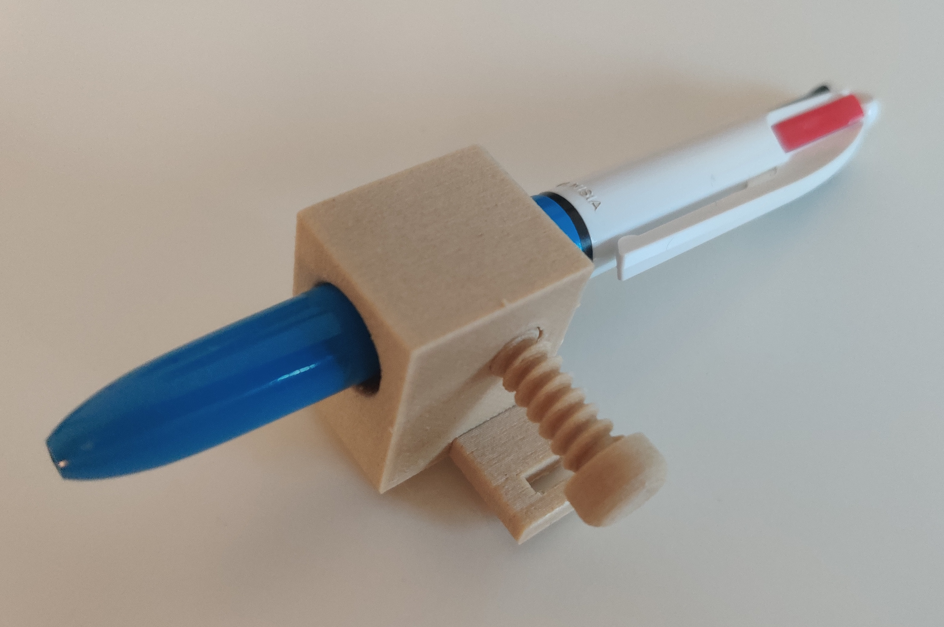
A thread could also be very useful to fix two parts without using screws. For this, a thread option is available, after clicking on it, simply choose the starting circle, if you want to extrude or cut the thread from/into the material, and choose the pattern:
Here is an example I have printed:
For a slightly more aesthetic look, the filet option can be used. Simply click on an edge of the part and select the desired angle of the thread:
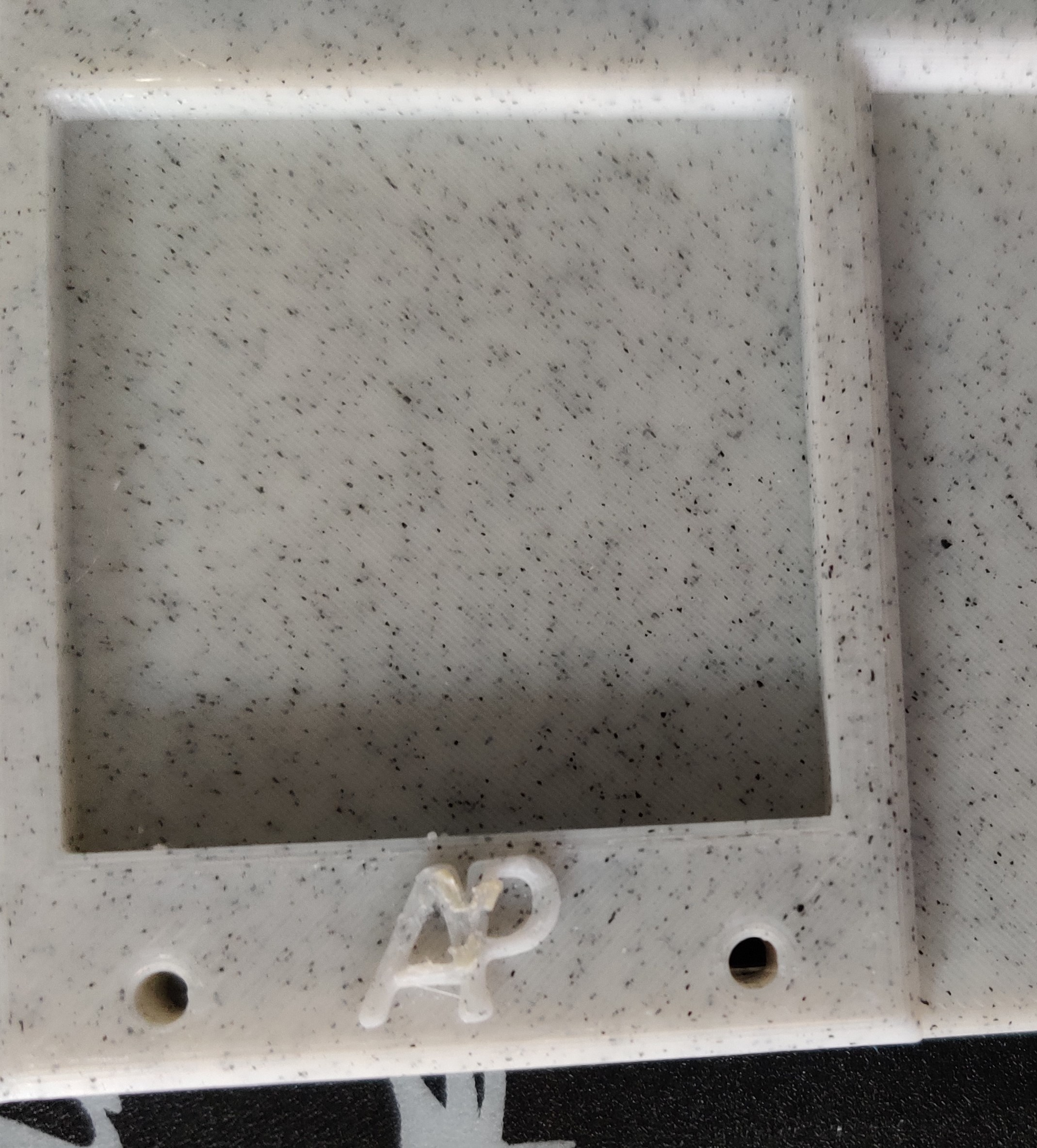
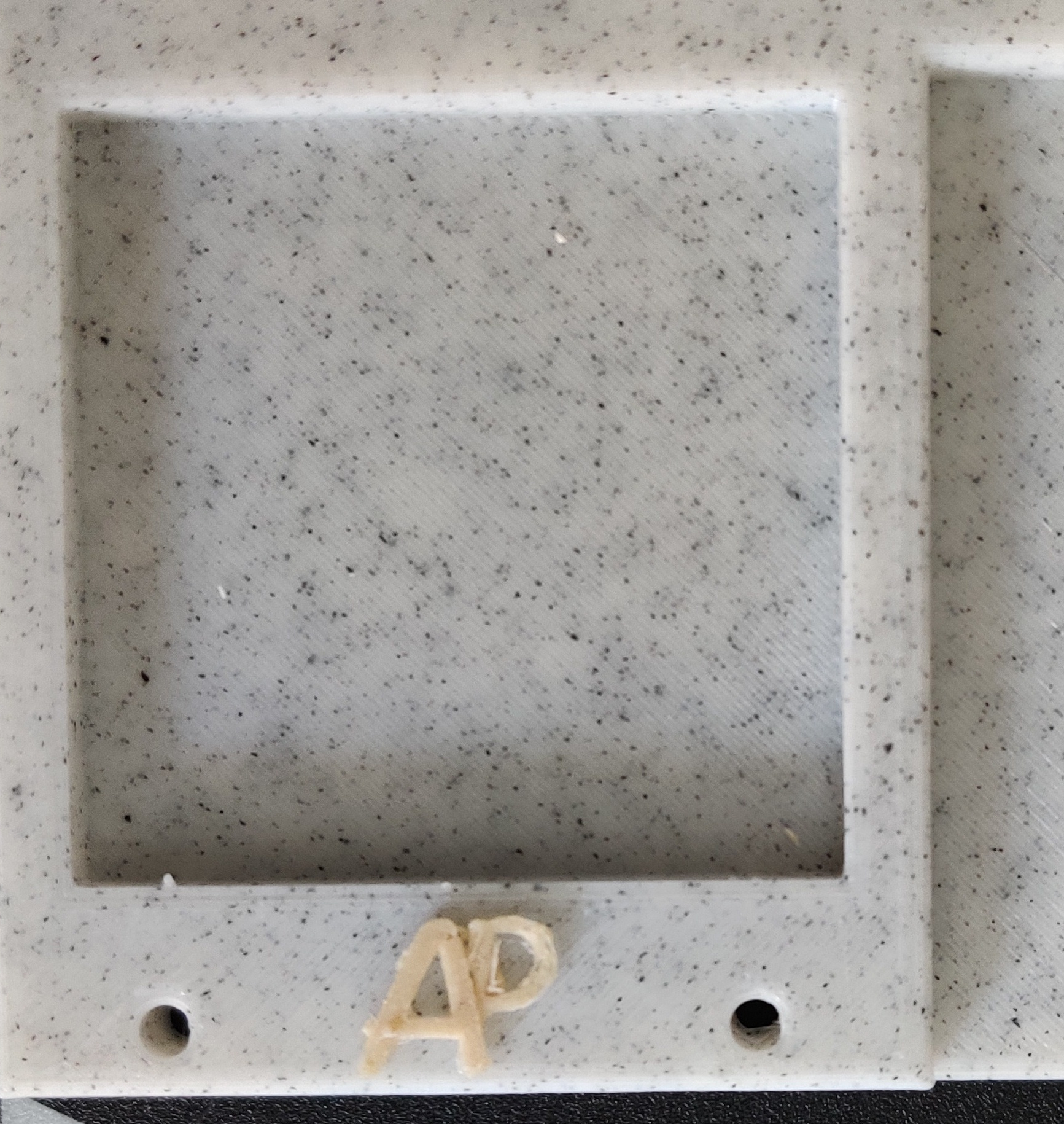
The last element I will show here is very useful if we want to insert an image/logo on a piece. To do this we need to open the sketch options and then choose sketch from image. Several options are available here, but the most interesting for binary logos is the one used in the following example. Solidworks draws the sketch by itself around a color. We can also add relief, I’ll show you an example with the logo of the site:
After modifying a bit the sketch, we can get something better:
We can then add the logo to any part as follow:
We will see in the next section how to convert these models to a format accepted by a 3D-printer, then how to print our logo in two colors.
2-c) Convert a part for our 3D printer
A 3D-printer can read a .gcode file. To create it from our Solidworks parts, we first need to export it into a .stl file. Then, we can open it with Cura software. Bunch of tutorial already exist online for the basics of Cura but I found less that explain how to print a piece in multiple colors.
I will show how I have printed the previous piece into 3 different colors: white for the whole block and wood/black for the logo. To do so, I need to stop the printer at a specific layer number to let me change the plastic spool. Instead to stopping it manually, I can insert in the .gcode file the command to stop the printer at the optimal layer numbers. To find these layer numbers, I had to cick on Slice button, then I went to the Preview section to determine the optimal layer numbers:

We can see that to print the logo in two different colors, I need to first stop the printer when it reaches the logo (layer n°31), then when it starts the ‘A’ (layer n°35). The following gif shows how to insert the pause in the .gcode file: extensions>post processing
The printer will then stop at the defined layer numbers and go to the specified position:
We can then change the spool color and resume the print. My first spool was white, the second one Wood, the third one Black:

The next section will show how to create one part from another and the geometry of constructions to help make mirrors.
2-d) Some parts creation in V1 machine
I used some of the features described in the previous section to create the machine. For example, I used the mirror option to create the profile support. This part was created from another one: the profile itself. To make sure I had the right dimensions for my profile holder, I decided to develop the part from the profile. As the profile 2040 is symmetrical between the x and y axis, I only had to sketch on 1/4 of the part and then use the mirror option:
I also had to create a certain geometry of constructions to make mirrors. For instance, I can show you how I constructed the belt notch for the profile support:

Here is the final V1 machine:
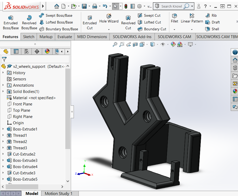
2-e) Parts creation in V2 machine
For the V2 machine, I tried to reduce a lot of material to save plastic. I also wanted to avoid using profiles to make it more portable. Finally, I wanted this machine to be easy to assemble so that I could take it apart for storage and then quickly reassemble it for use.
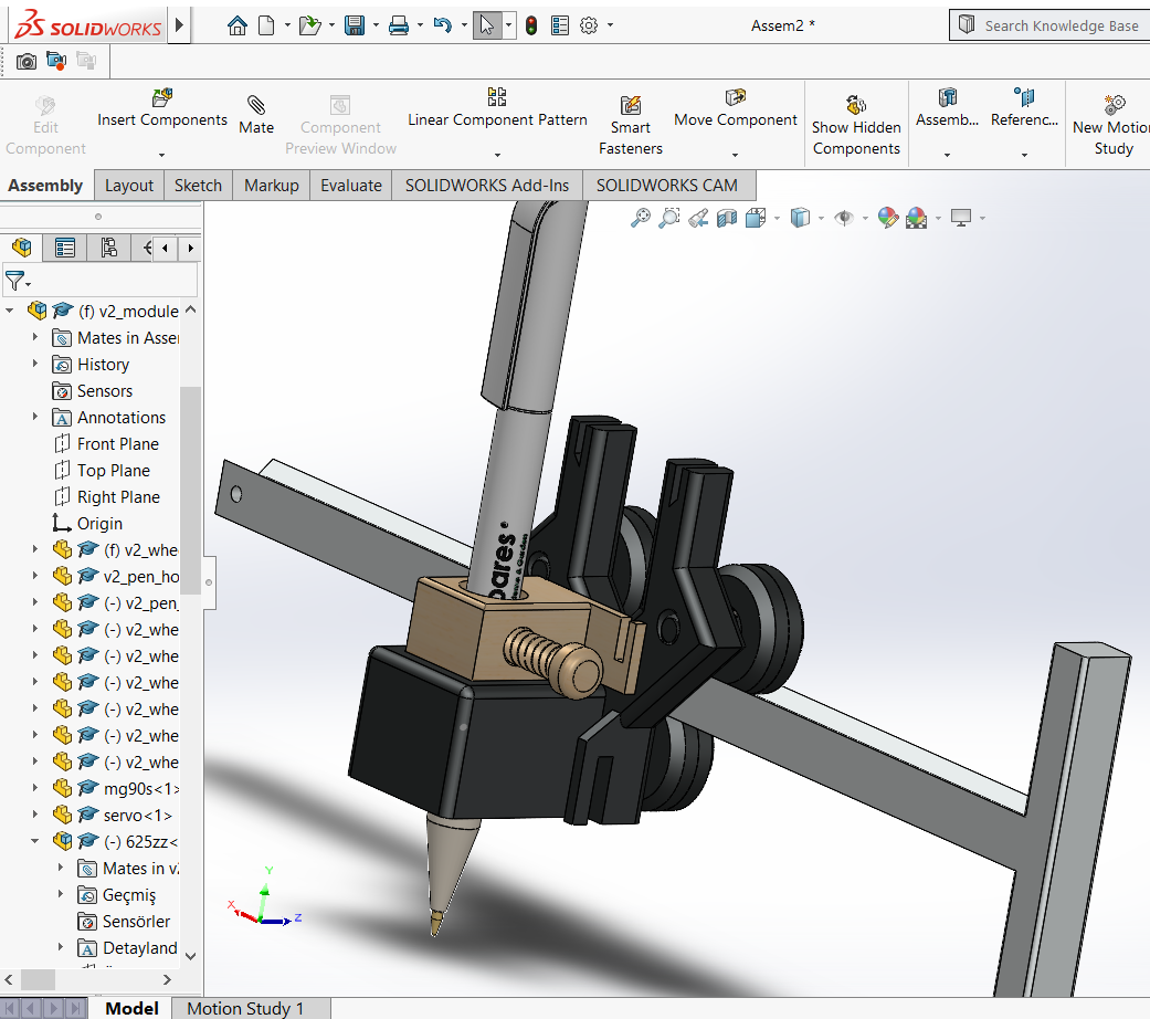
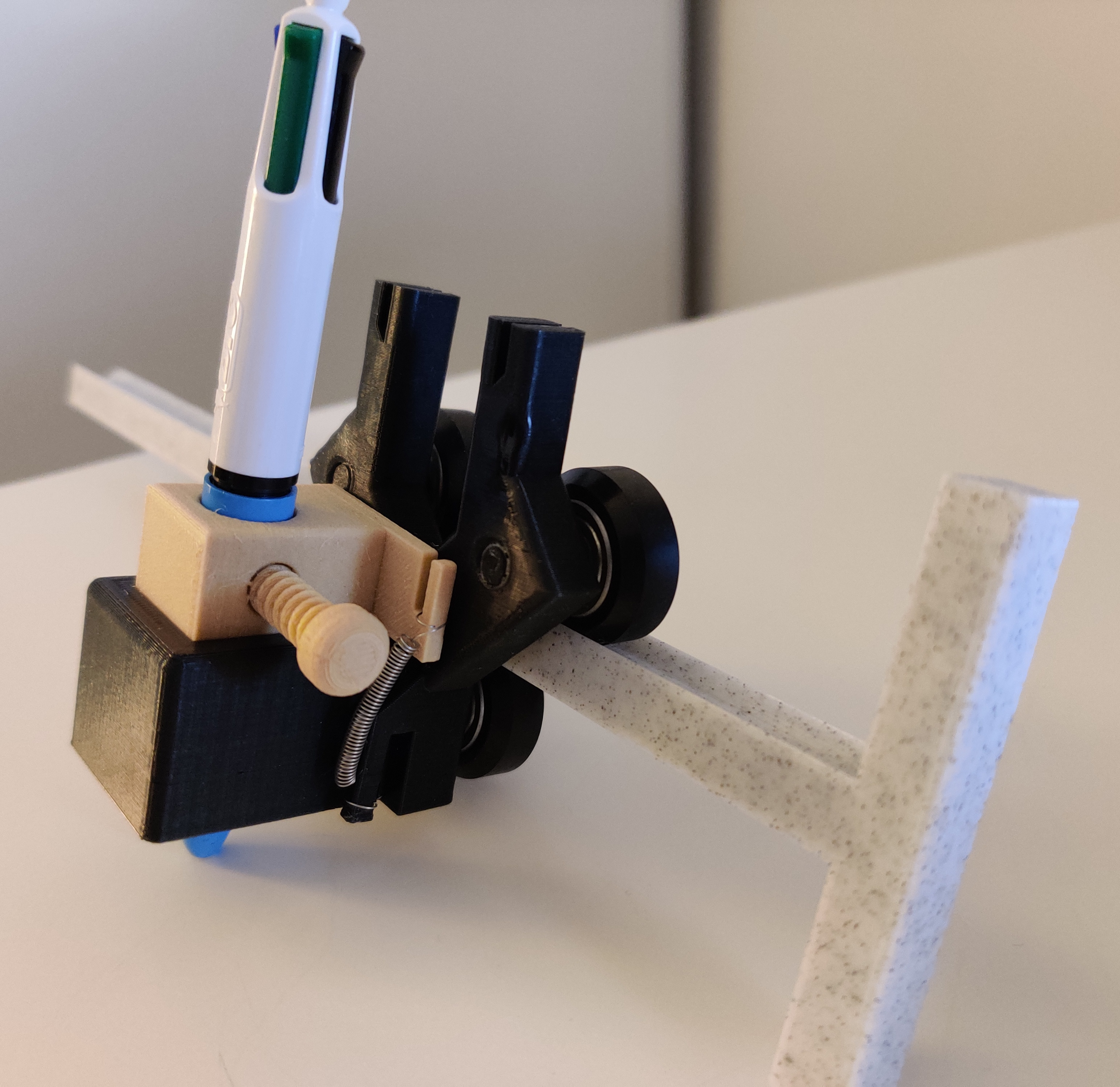
For this version, instead of showing a simple feature used when creating a part, I wanted to show how to build a complete assembly composed of several parts. I chose to record how I built the module that holds the pencil because it was the most complete part of the machine. It’s a 1h video that I accelerated to a few minutes:
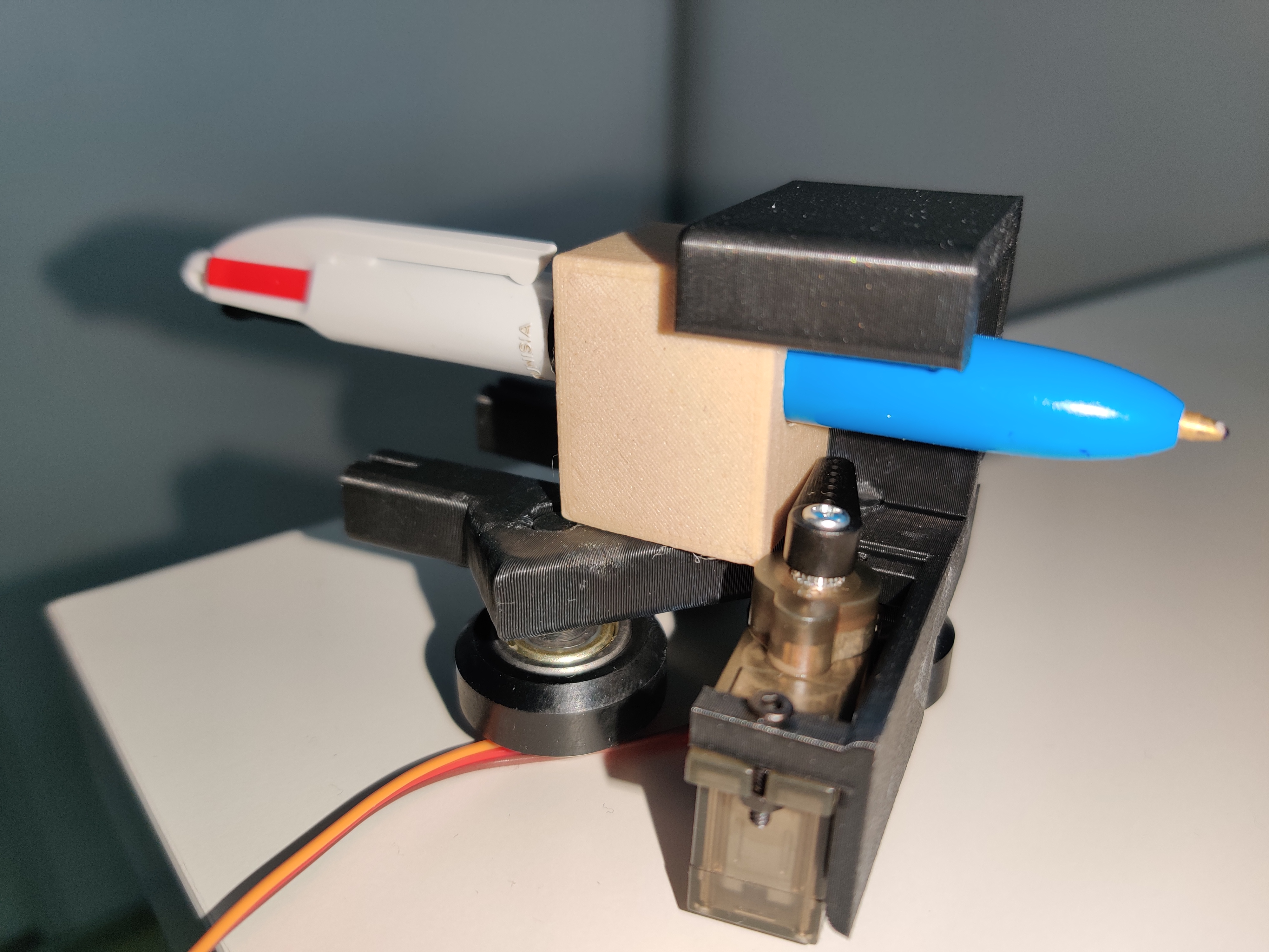
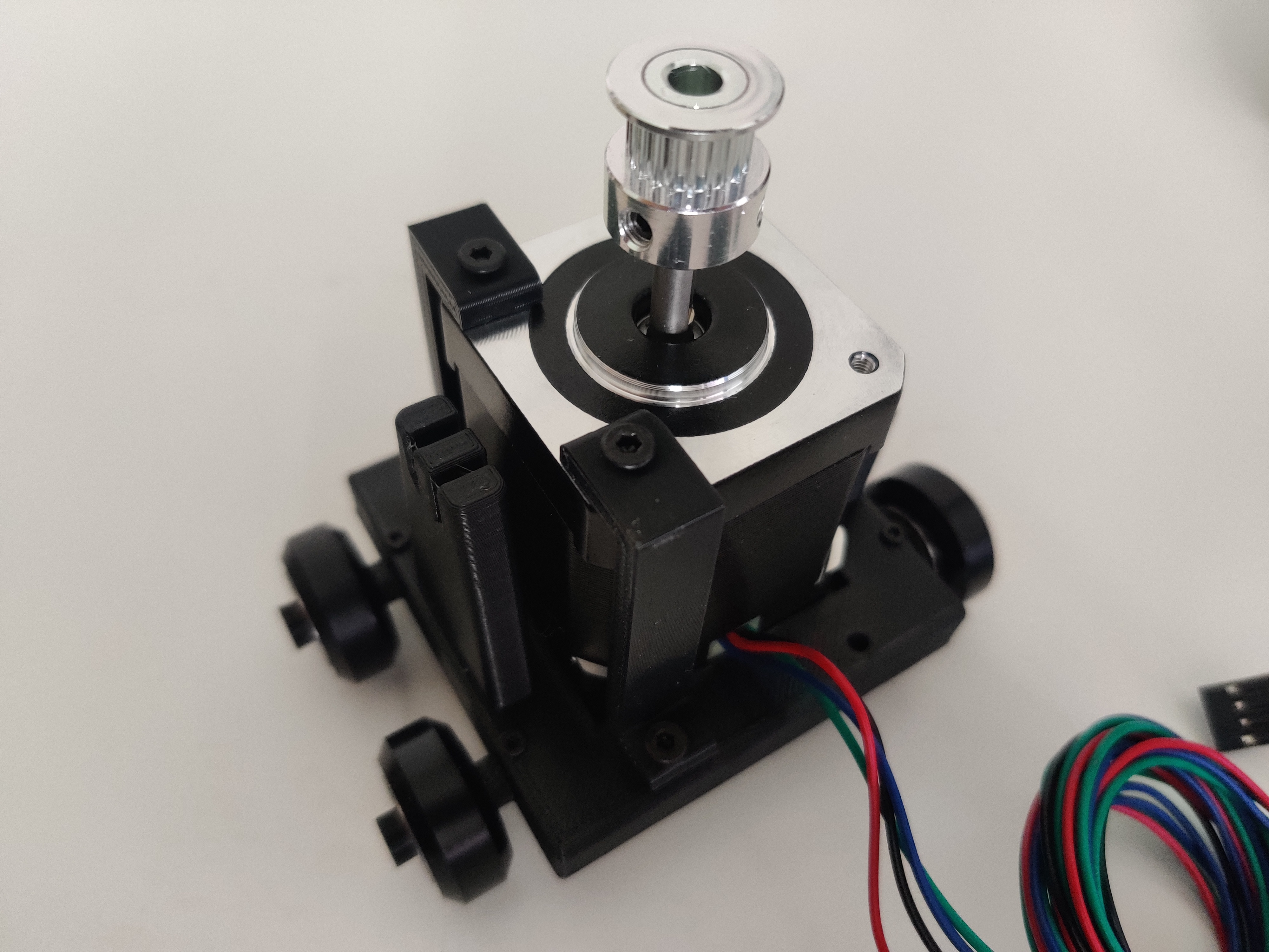
Here is the final module:
3) Printing
As I showed previously the creation of the module, I will also show its two main parts’ printing.
The module support:
The three pieces in blue to carry the wheels:
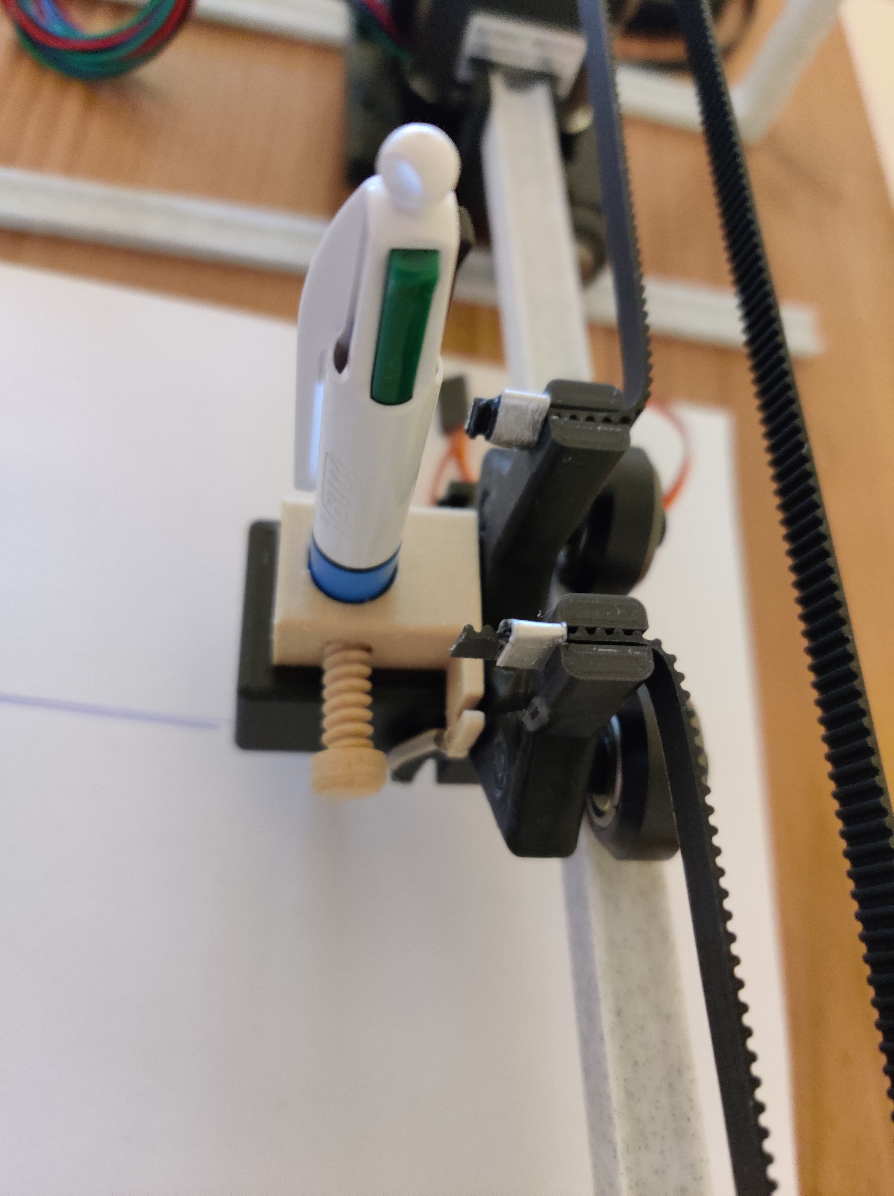
The pen holder:

4) Assembly
4-a) Module assembly
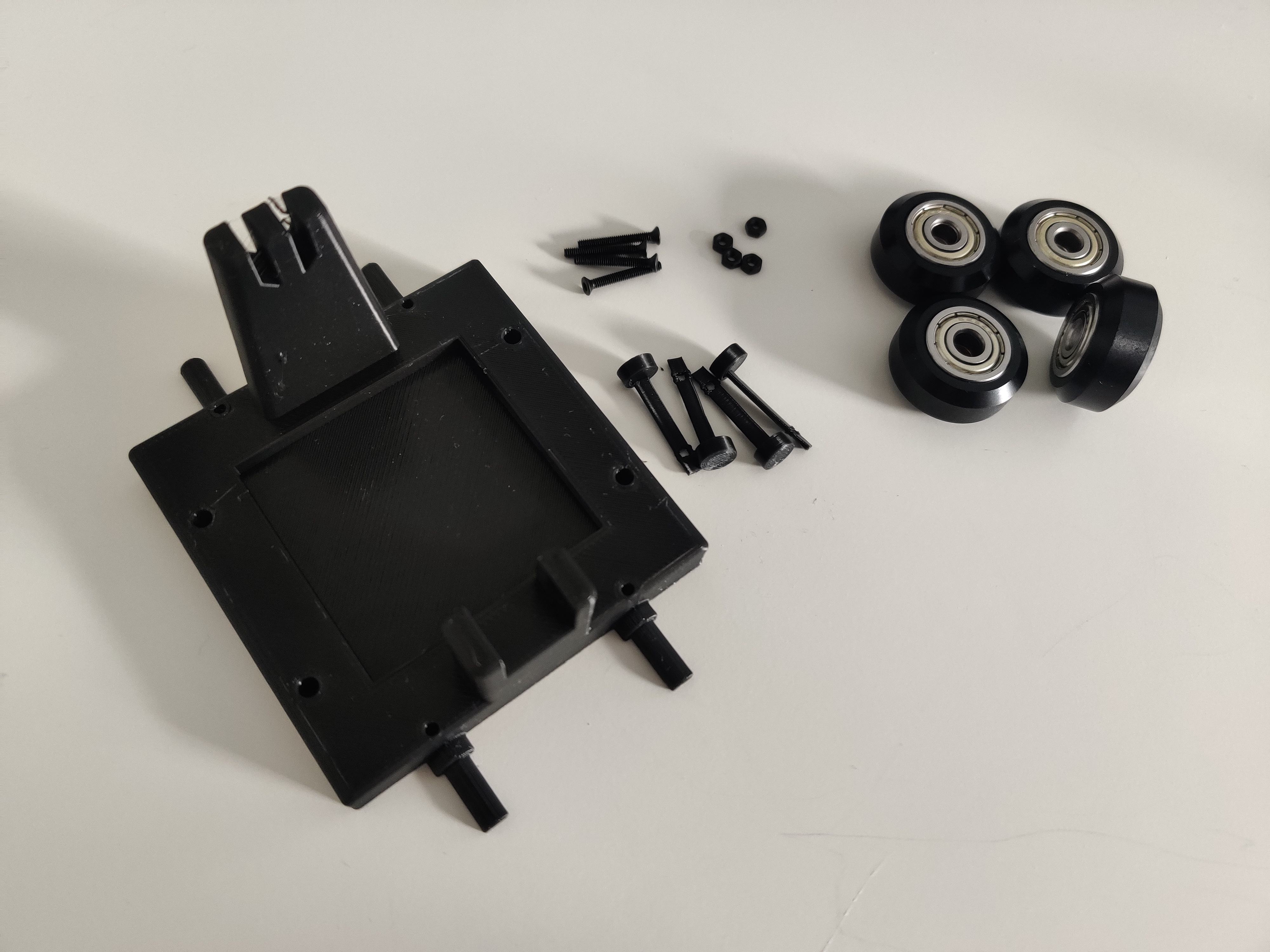
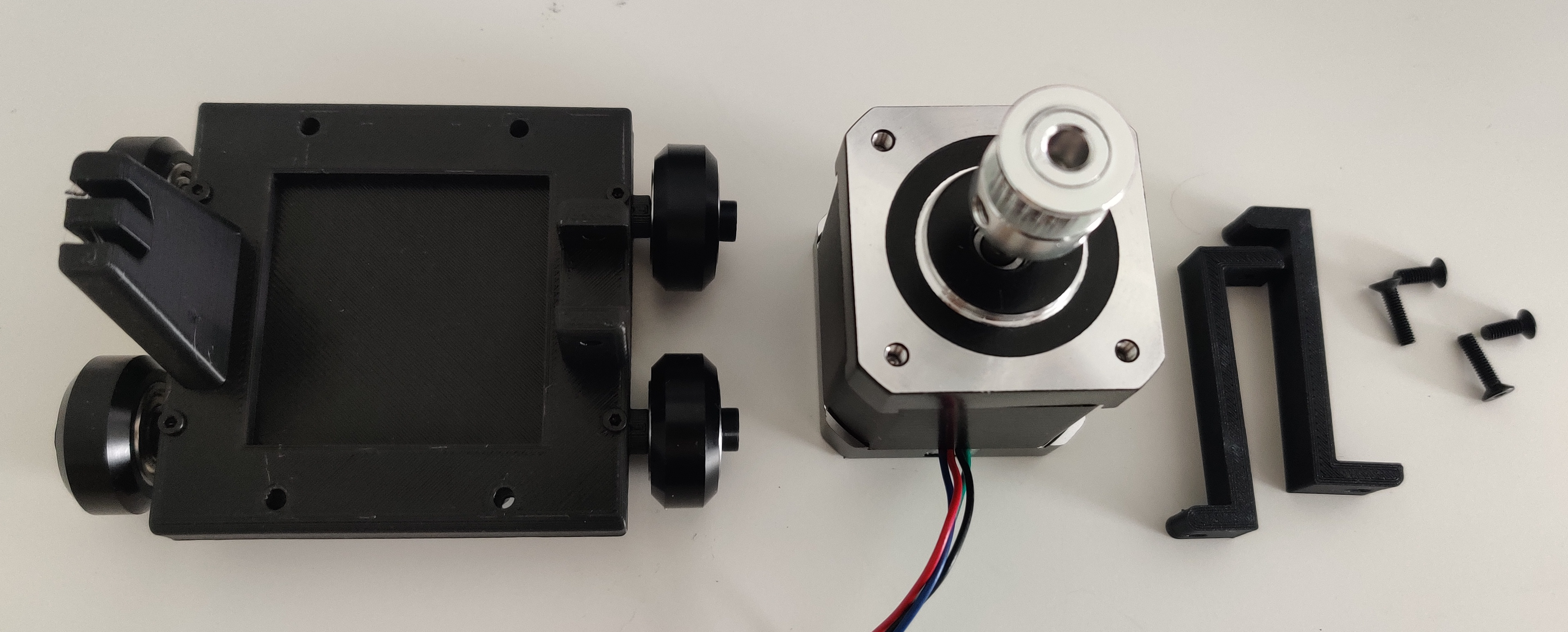
All the needed parts to built the module are presented here:
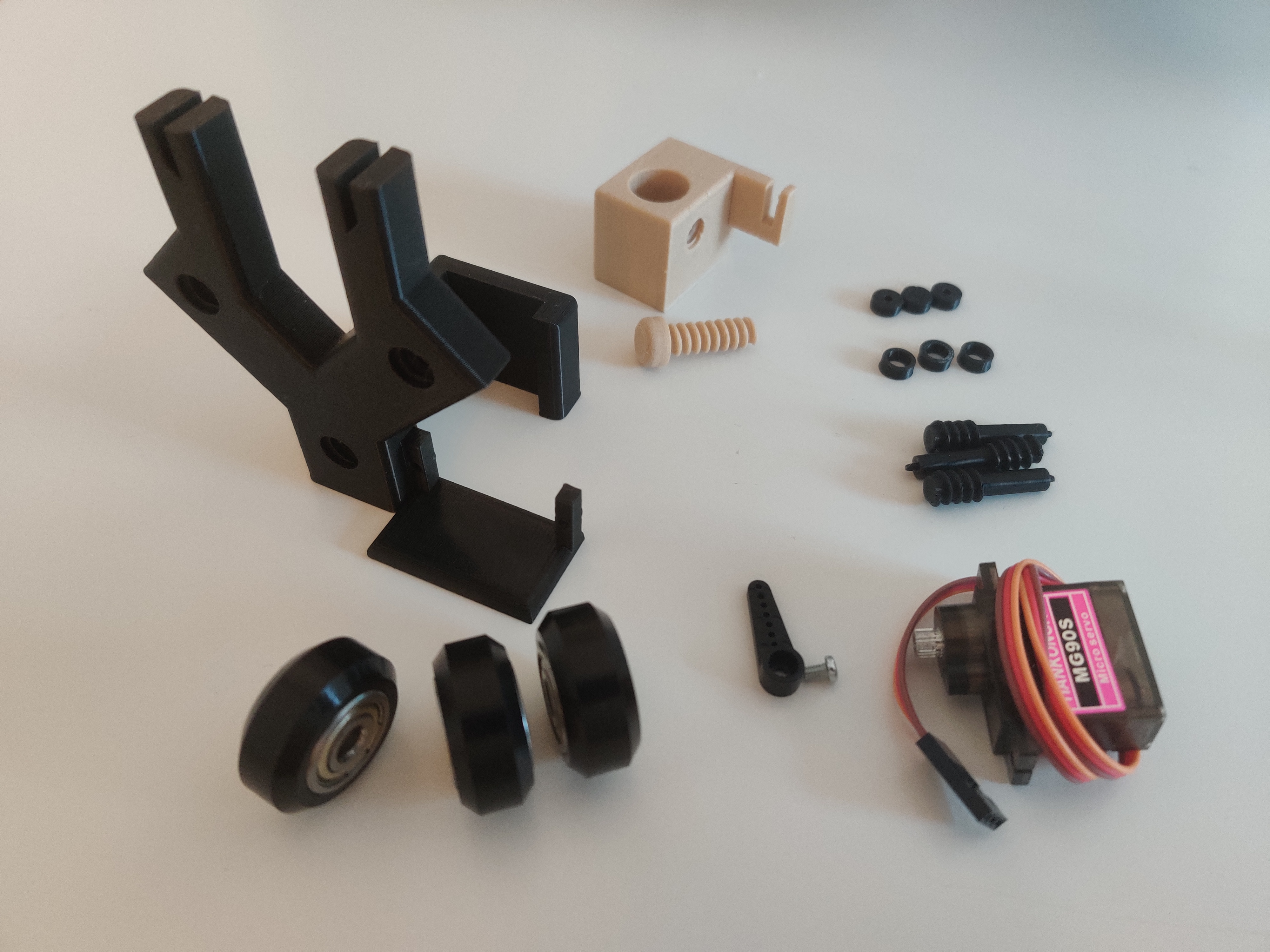
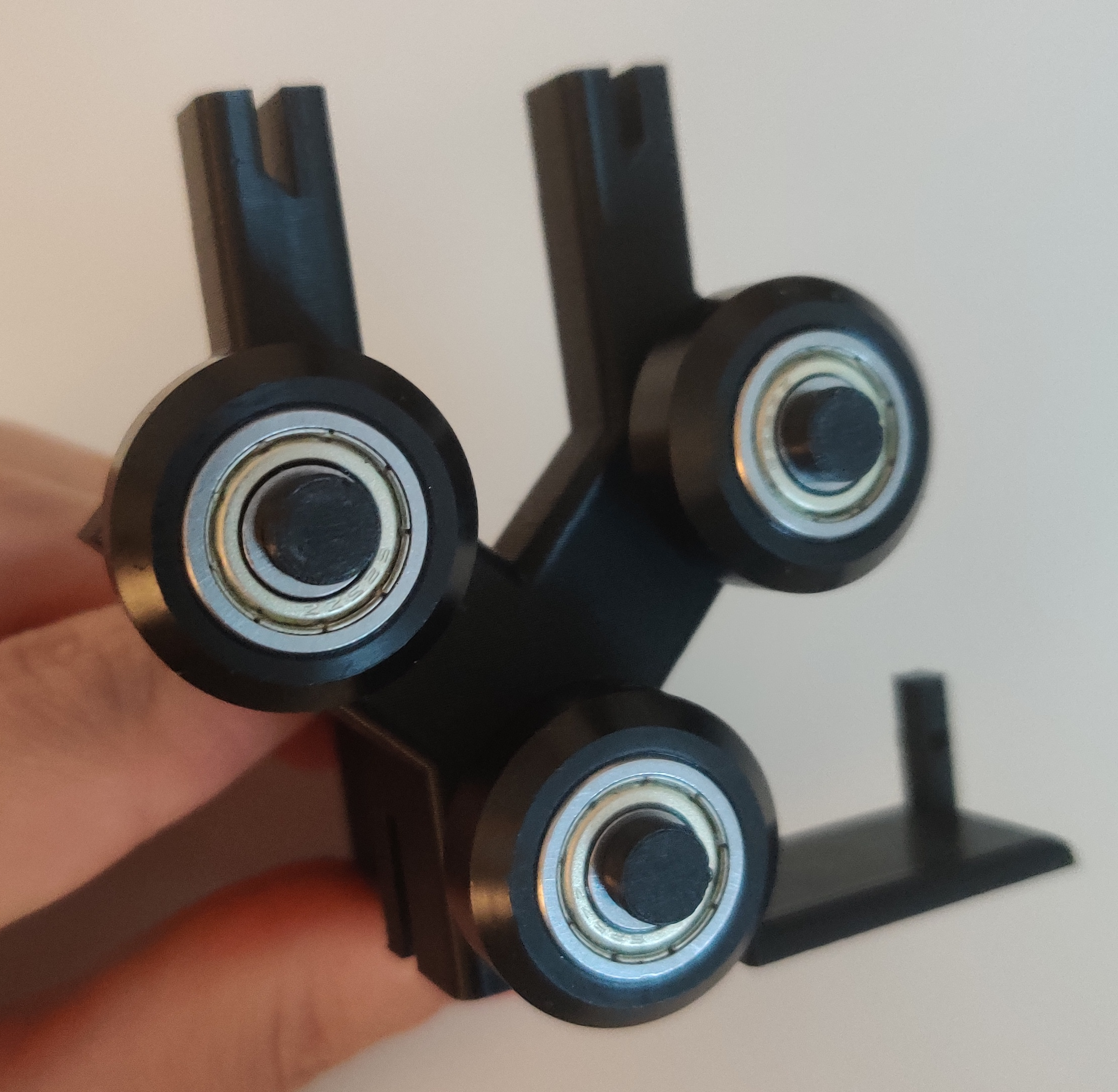
First we need to fix the three wheels as follow:
Then we can add the pen on the pen holder:
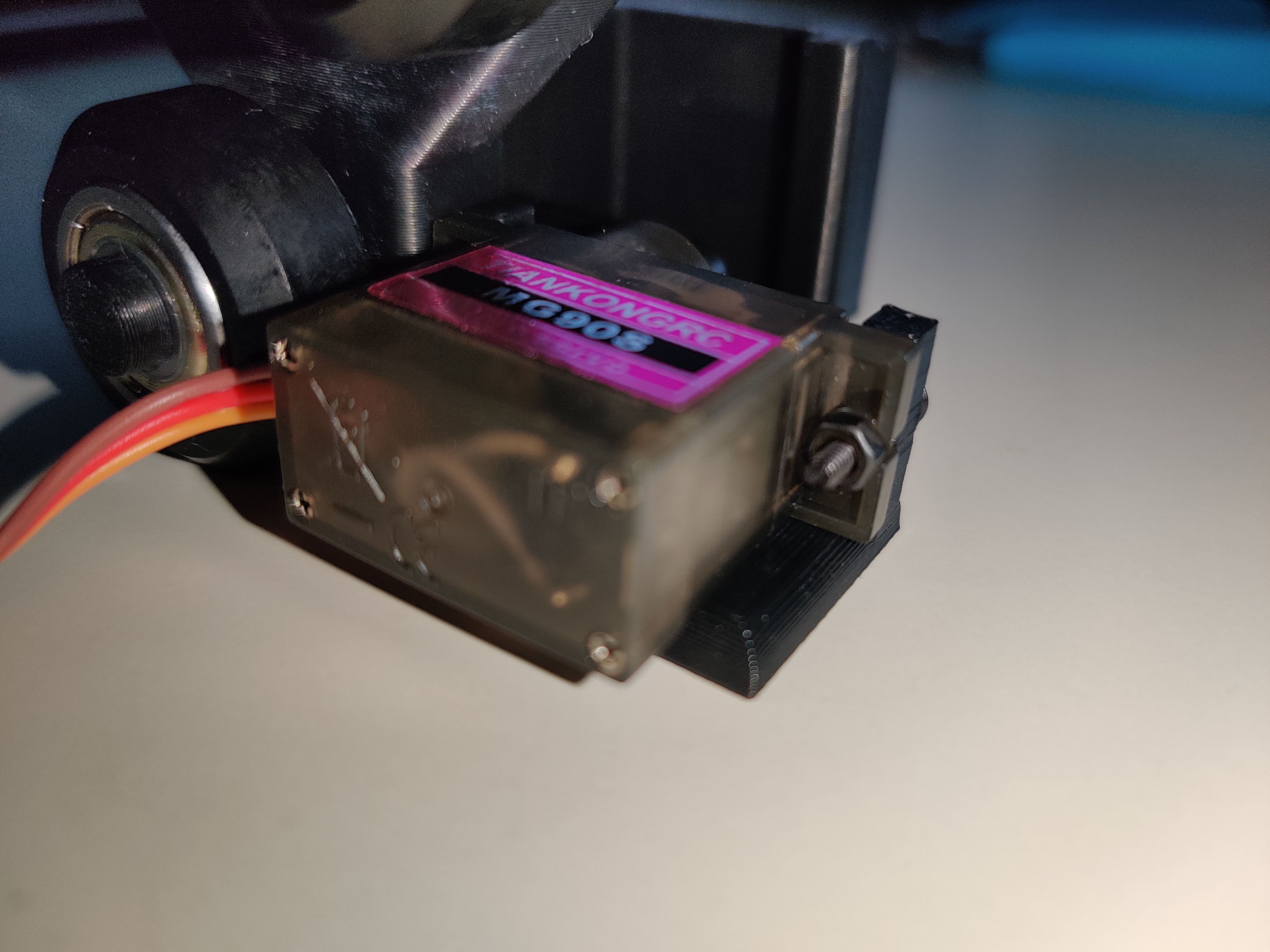
Once the servo is attached, the module is assembled:

We can then verify the good dimension of the axis:

Here is the final comparison of the module Solidworks – Real:
4-b) Y-axis assembly
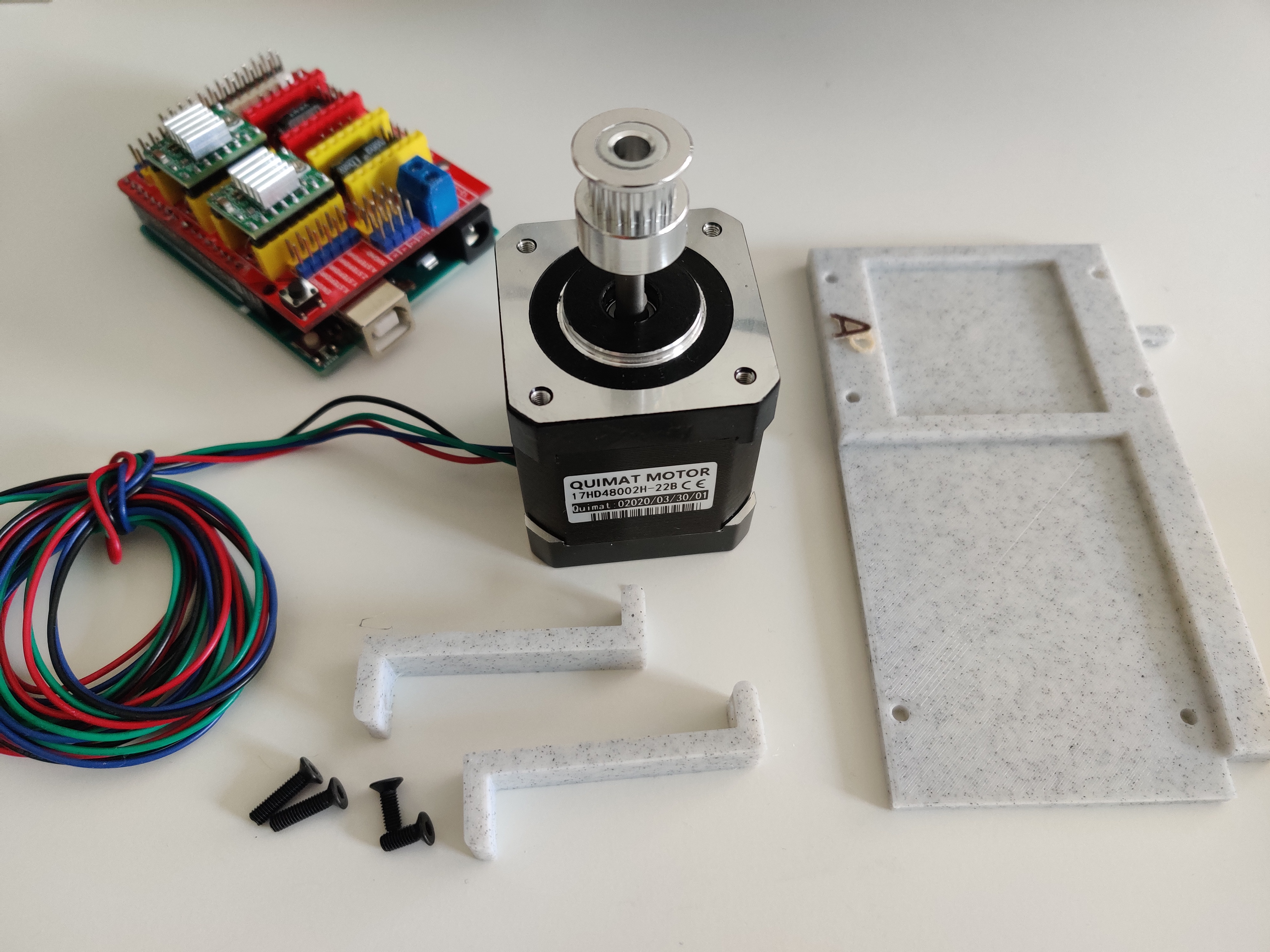
First we need to get the needed pieces for the y motor support:
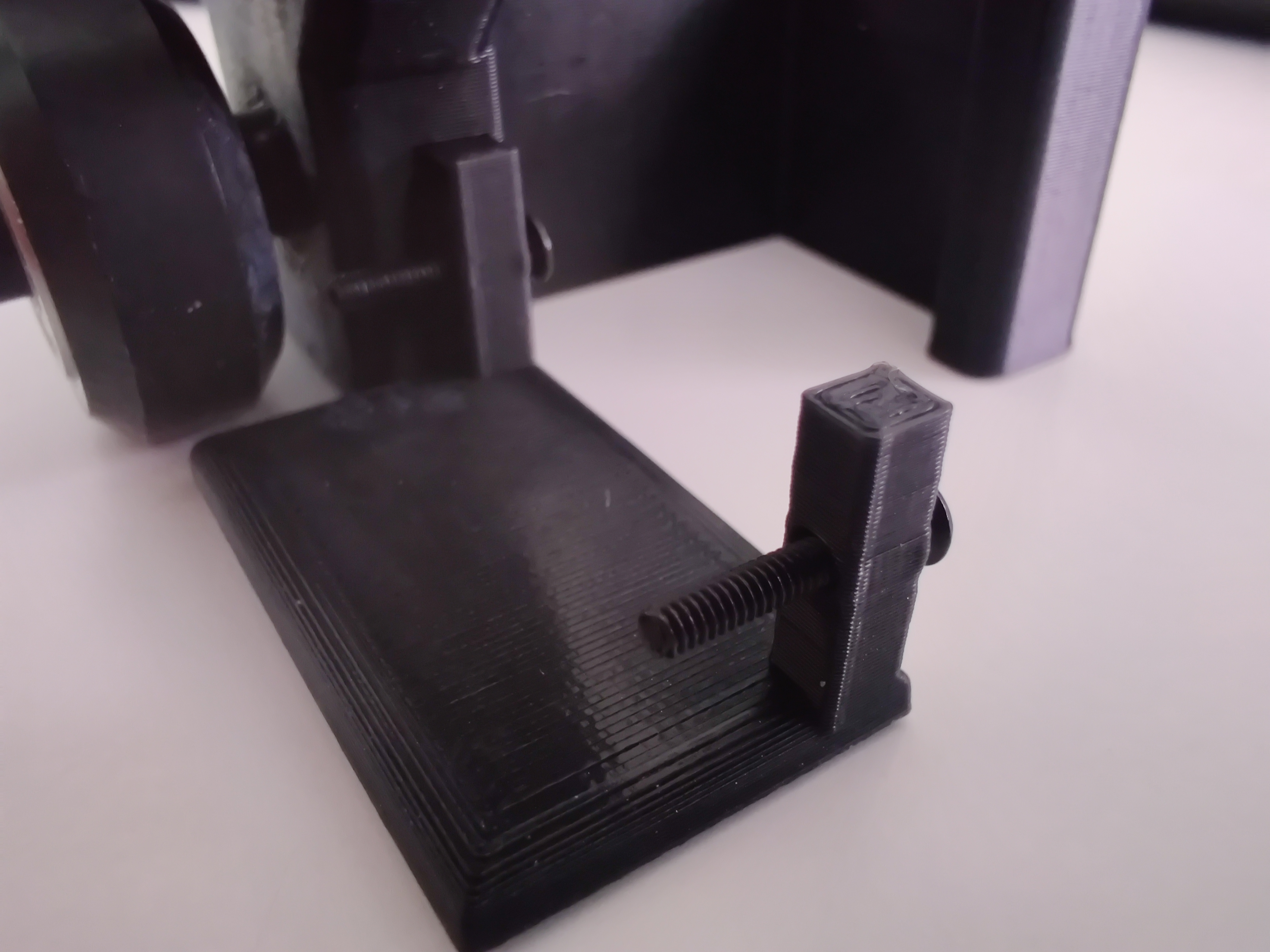
We can assemble it as follow with M2 screw and a nut


We can then verify that the motor support is rolling well:
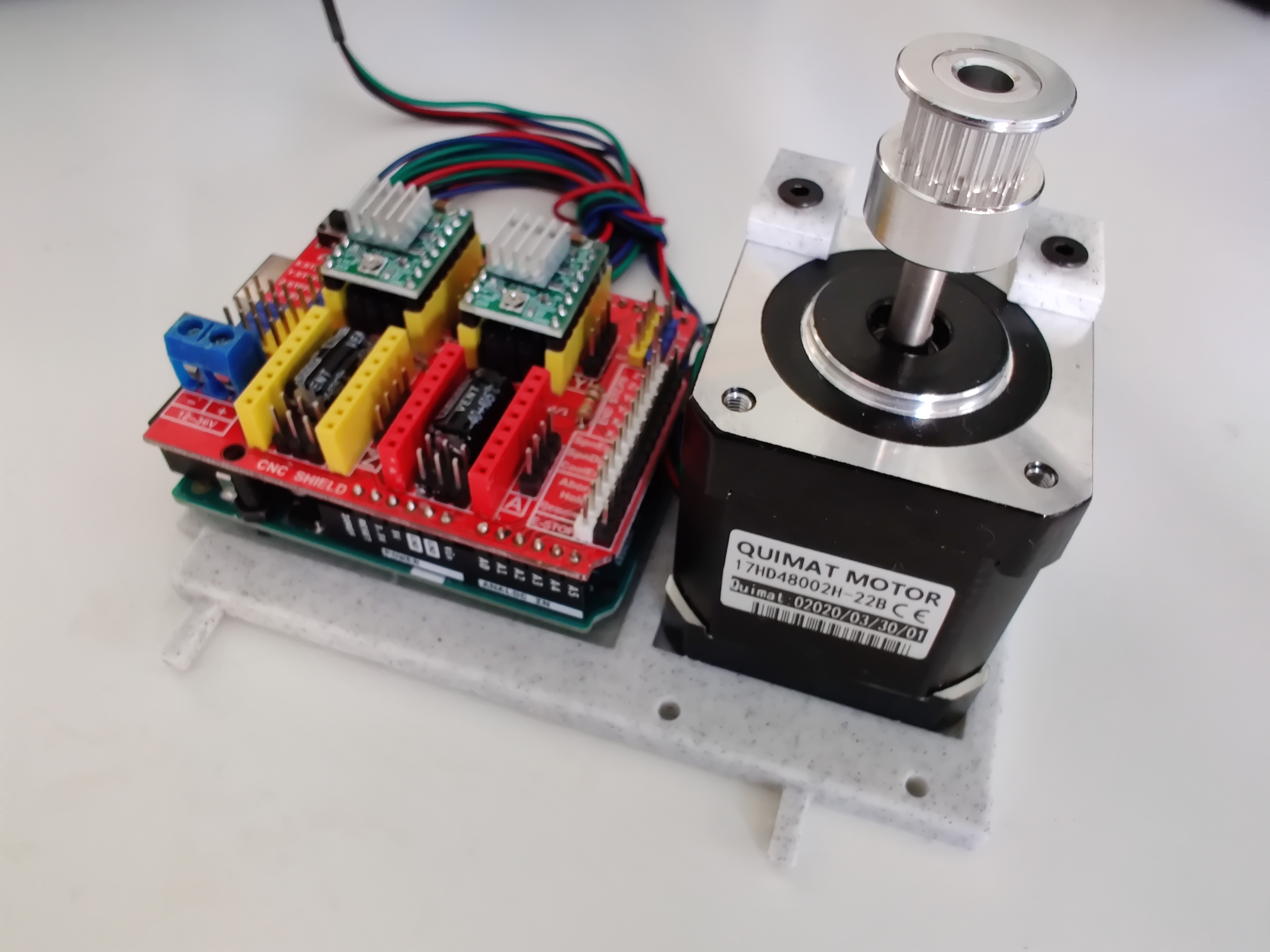
We can finish with the motor itself with these pieces:

The Y-axis is now, we will install the belt once everything is built:
4-c) X-axis assembly
For the x-axis, we first need the following pieces:
We can add the blocks to avoid the engine movements:

Then the screws and nut to fix the electronic board:


4-d) Addition of the belts
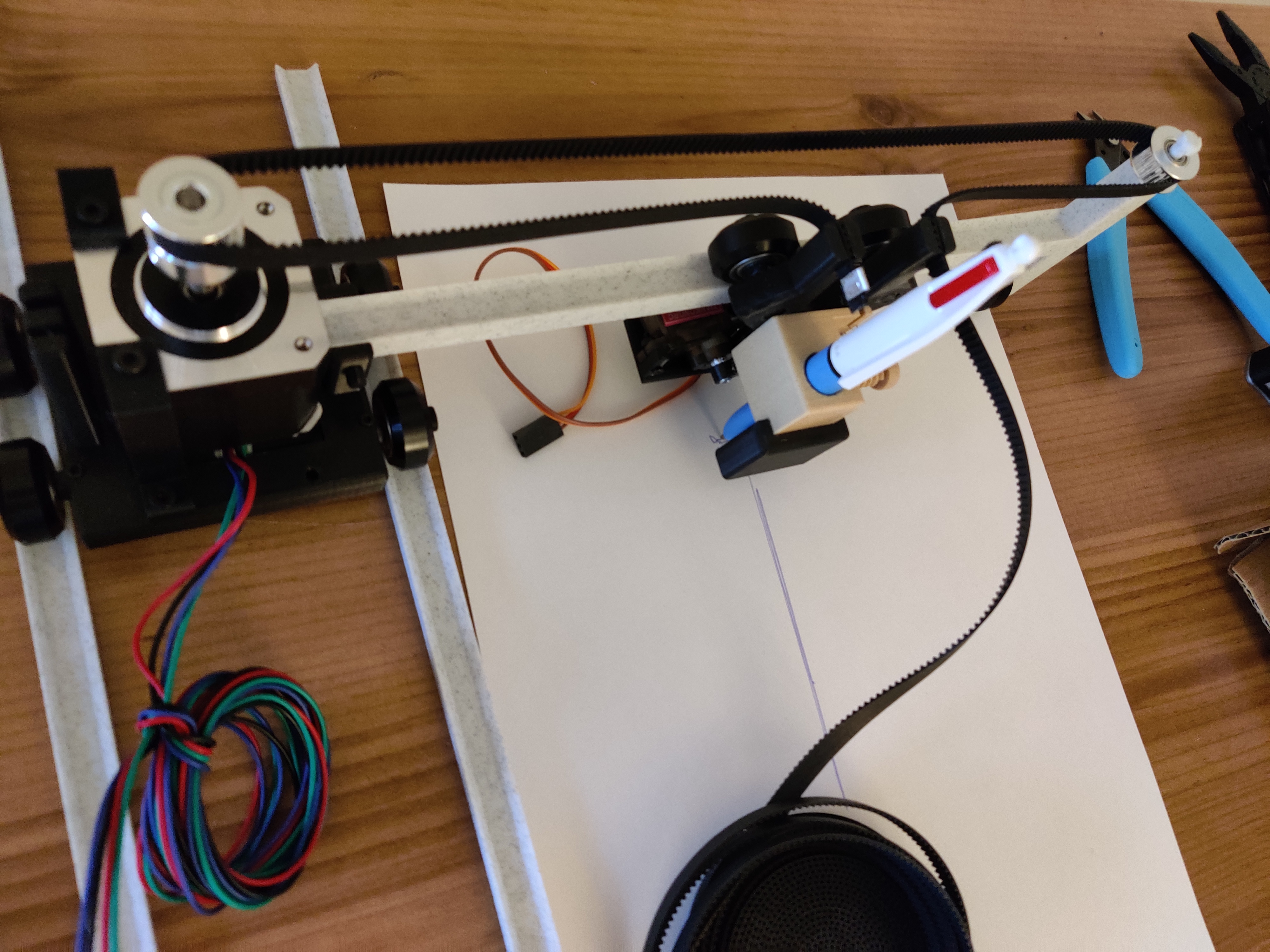
Here are all the parts needed to complete the assembly of the machine:
We can first put the axle in the main part with the electronic board and check that the track gauge is correct:
Then we can add the y-axis:

And check that the machine is working:
Once the two axes are assembled, the belts can be added. First of all, to avoid using glue, we need an aluminum piece to be added at both ends of the belt. This aluminum piece will allow the belt to get stuck in the notches:
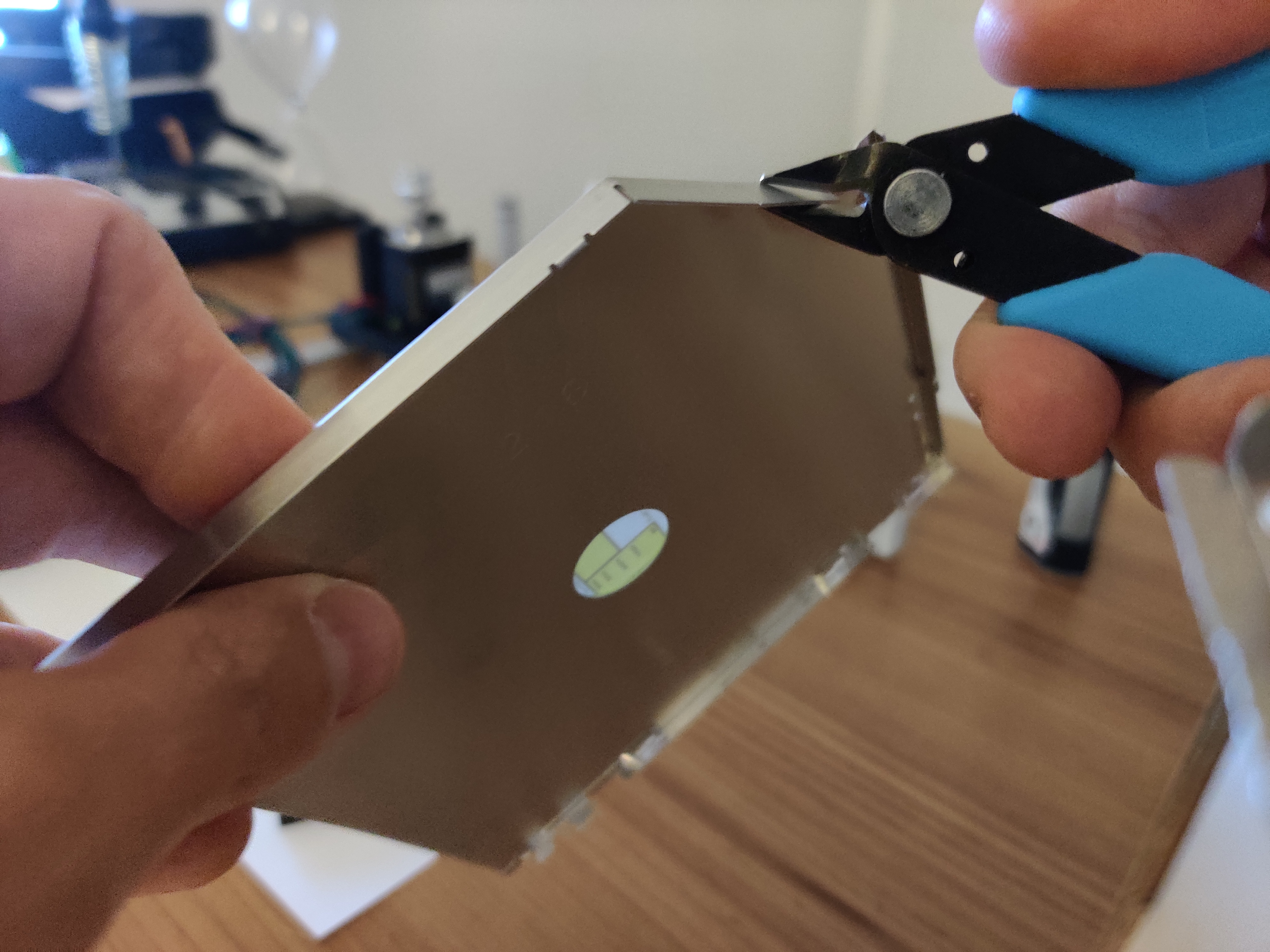
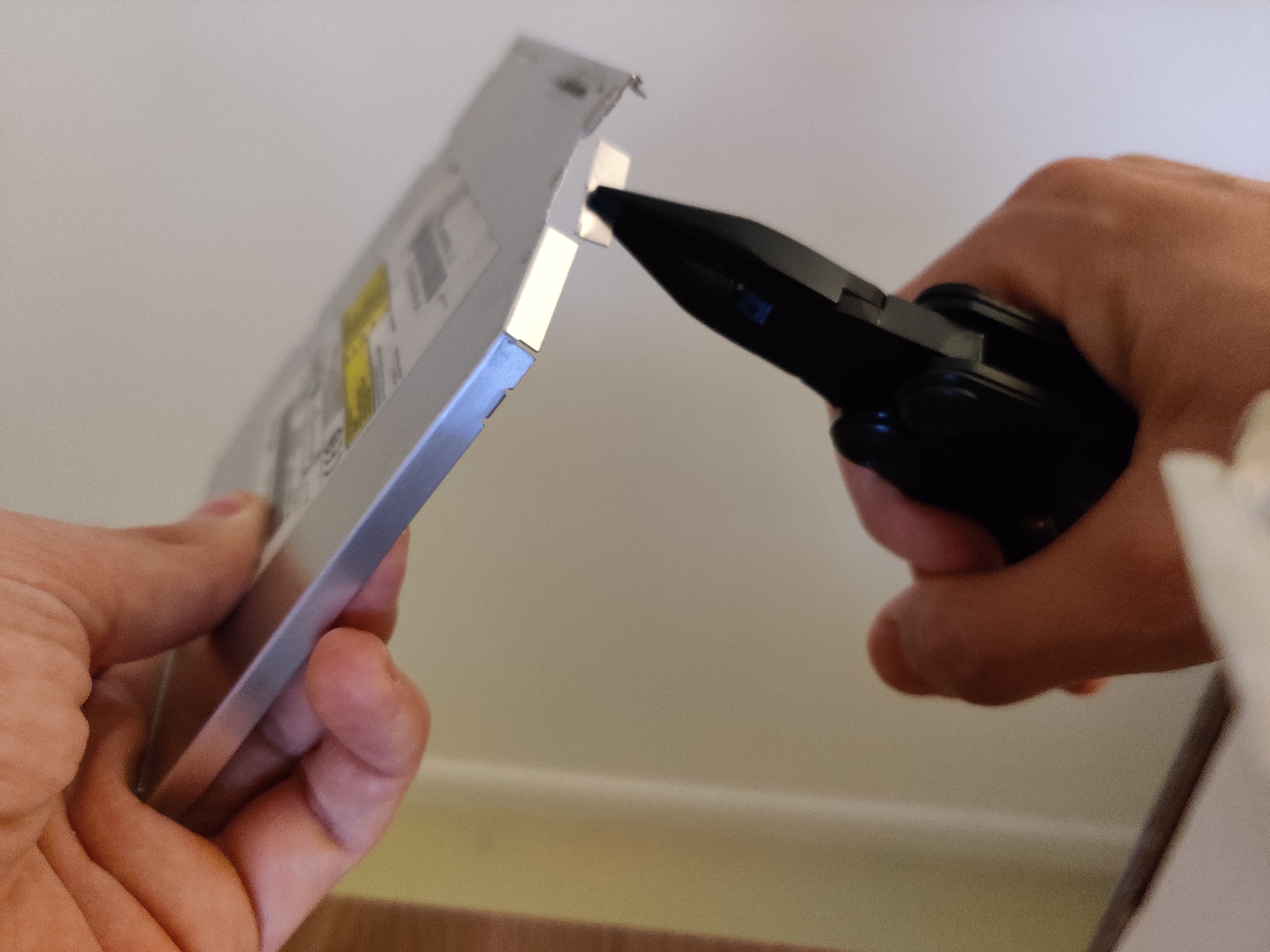


The right belt length can then be cut for both axes:

The machine is now assembled. We can start checking that we can control the motors and send him a .gcode. Gcode contains the commands to send to the motors and the servo to draw something.

5) Motors and servo control
Many solutions exist to control such a machine with two stepper motors and a servo. I chose to use an arduino, a CNC shield (a board designed to control a CNC machine) and two a4988 drivers motor.
With these two electronic boards, I got the hardware dedicated to control a drawing/engraving/CNC machine. I could then use Open Source software to control them or use Open Source code to send any drawing path to the Arduino.
As this was more a modeling project than a software project, I simply used a software named Benbox to send drawings to my machine. Here are the steps to make it work:
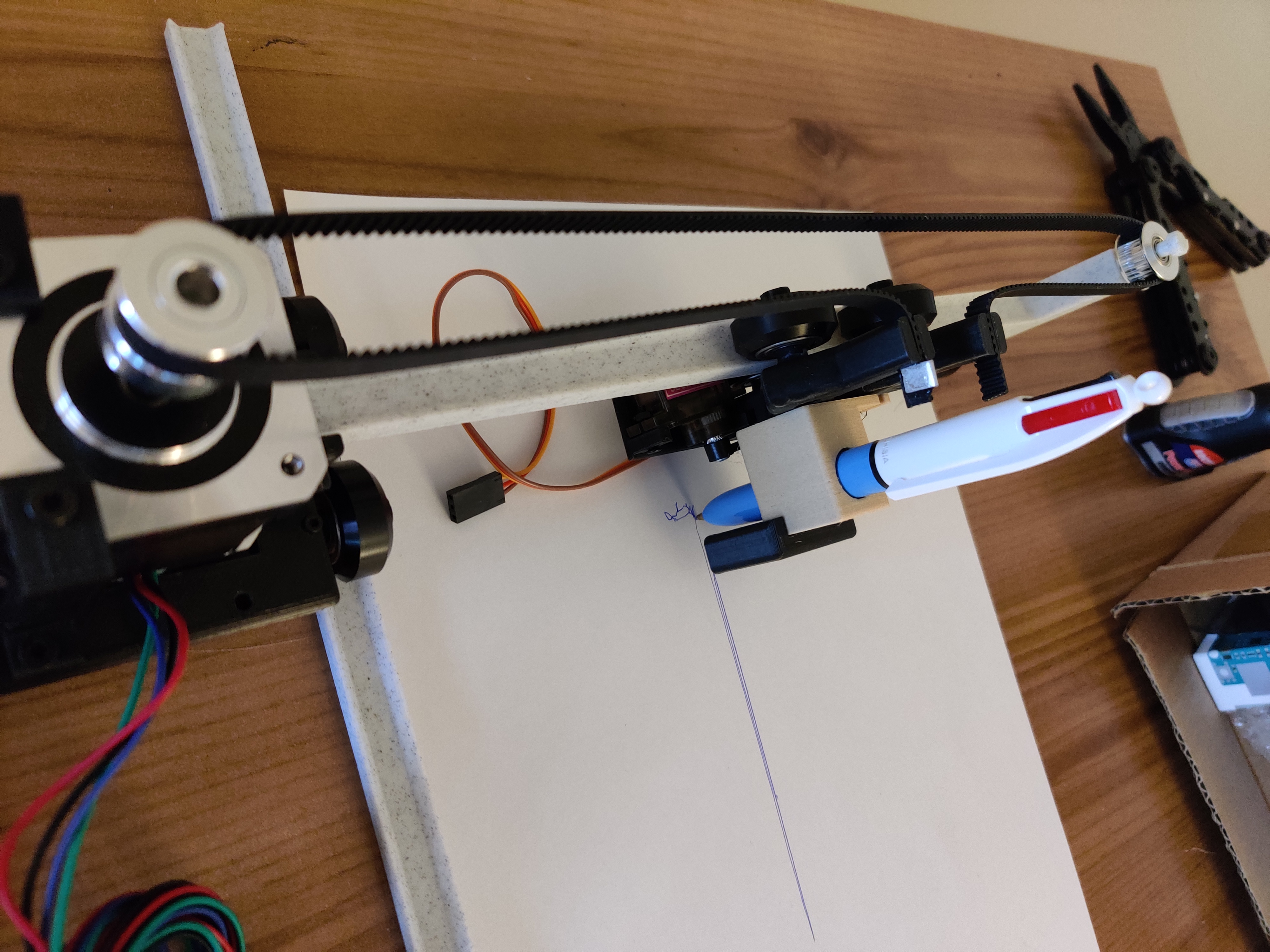
6) Result
Here are some drawings I have done with the machine:

7) Upgrade to engraving machine
TODO
Here you can find my project:
https://github.com/Apiquet/drawing_machine
